Chatter marks in high-speed face milling are a persistent challenge in the machining industry. According to a report from the International Journal of Machine Tools and Manufacture, approximately 30% of surface defects in machined components are attributed to chatter. Understanding what causes chatter marks during high-speed face milling is essential for maintaining product quality and improving machining efficiency.
Dr. Michael Thompson, a leading expert in machining dynamics, highlights, "Chatter is not just an annoyance; it can lead to costly rework and tool wear." This emphasizes the importance of addressing this issue. Factors such as tool geometry, cutting speed, and machine rigidity all play significant roles in generating these undesirable marks. In essence, optimizing these parameters is crucial to minimize chatter occurrence.
However, despite advancements, a perfect solution remains elusive. Many engineers grapple with finding the right balance between speed and stability. The need for continual exploration and adaptation in milling techniques is evident. As the industry evolves, ongoing research will be vital to uncover the intricate dynamics of what causes chatter marks during high-speed face milling.
What Are Chatter Marks in High Speed Face Milling?
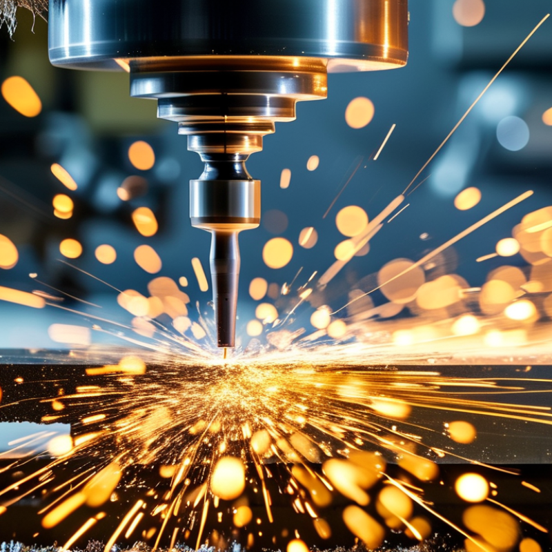
Chatter marks in high-speed face milling are distinct patterns that appear on machined surfaces. These marks result from vibrations occurring during the milling process. When cutting tools interact with the workpiece, variations in force can lead to oscillations. This causes an uneven finish and impacts the final product's quality.
Understanding chatter marks requires insight into the milling dynamics. Factors like spindle speed, feed rate, and tool geometry contribute significantly. High spindle speeds can amplify vibrations, intensifying chatter. Additionally, a tool with improper clearance or worn-out edges may exacerbate the issue. Operators must remain vigilant, as unnoticed chatter can lead to increased tool wear and poor surface integrity.
Operators need to keep an eye on their setups. Adjusting parameters like cutting speed or tool paths can mitigate unwanted chatter. Regular monitoring and adjustments are key. Chatter marks serve as a loud reminder of the delicate balance in milling operations. Addressing these marks isn't just about fixing surface quality but also about improving overall machining efficiency.
Understanding the Mechanisms Behind Chatter Formation
Chatter marks in high-speed face milling arise from complex vibration phenomena during machining. Understanding these mechanisms can significantly enhance manufacturing quality. Chatter typically occurs when the spindle speed, tool geometry, and workpiece material resonate with each other. A study by the American Society of Mechanical Engineers (ASME) reported that 80% of machining errors are linked to vibrations like chatter.
Machinists often overlook the importance of maintaining optimal cut parameters. Excessive speed or inappropriate tool path can exacerbate the issue. Research indicates that maintaining a consistent feed rate and utilizing appropriate cutting speeds can reduce the likelihood of chatter. For instance, findings from the Journal of Manufacturing Processes reveal that adjusting the spindle speed by just 10% can yield a notable reduction in chatter frequency.
Analyzing chatter formation requires a multi-faceted approach. Consider conducting regular tool maintenance and inspecting machine components for wear. Improper tool alignment could also contribute to these vibrations. A technical report by the International Journal of Advanced Manufacturing Technology emphasizes the need for precise setups, indicating that a 0.1 mm misalignment can increase the risk of chatter dramatically. Addressing these nuances can lead to better control over machining processes, ultimately improving output quality.
Chatter Marks in High Speed Face Milling
Factors Affecting Chatter Marks: Tool Geometry and Material Properties
Chatter marks are a persistent issue in high-speed face milling, often resulting from a complex interplay between tool geometry and material properties. The design of the cutting tool plays a crucial role. Sharp edges may lead to excessive vibrations, causing unintended chatter marks on the machined surface. Conversely, a dull tool can cause increased friction, also contributing to irregularities. The balance between sharpness and stability is delicate yet vital.
Material properties also significantly influence chatter. Harder materials can amplify vibrations during machining, while softer materials may dampen them. Each type of material reacts differently under high-speed conditions, affecting the overall milling process. For example, aluminum runs smoother than titanium but requires careful attention to speed and feed rates. Misjudgments in tool selection or cutting parameters can lead to undesirable outcomes.
Specific cutting angles can either mitigate or exacerbate these problems. Different shapes in tool designs may have their advantages and disadvantages in various machining scenarios. Furthermore, the wear on tools can create inconsistent results over time. Understanding these factors can improve machining effectiveness and surface quality. This consideration highlights the importance of continual learning and adaptation in milling practices.
Vibrational Frequencies and Their Role in Chatter Marks Occurrence
Chatter marks in high-speed face milling are a complex issue caused by vibrational frequencies. These vibrations occur during machining and can lead to visible patterns on the workpiece surface. Understanding the vibrational frequencies at play is essential for effective milling.
The frequency of the cutting tool and the workpiece interact, sometimes resonating at certain points. When the tool's frequency matches the natural frequency of the cutting system, it intensifies vibration. This phenomenon can create detrimental chatter marks, impacting surface quality. The result is often an uneven surface finish, which can compromise the integrity of the workpiece.
Machinists must assess their equipment and cutting parameters closely. Adjusting speed, feed rate, and tooling can help mitigate these issues. Establishing the right balance is crucial; however, achieving this balance is often challenging. Every machining scenario presents unique conditions. What works well in one case may not be effective in another. It's a continuous learning process that demands careful observation and adjustments over time.
What Causes Chatter Marks in High Speed Face Milling? - Vibrational Frequencies and Their Role in Chatter Marks Occurrence
| Vibrational Frequency (Hz) |
Face Milling Speed (m/min) |
Chatter Marks Intensity (1-10) |
Tool Material |
Workpiece Material |
| 2000 |
120 |
8 |
Carbide |
Aluminum |
| 2500 |
150 |
7 |
HSS |
Steel |
| 1800 |
100 |
5 |
Carbide |
Titanium |
| 3000 |
200 |
9 |
Ceramic |
Copper |
| 2200 |
130 |
6 |
HSS |
Plastic |
Mitigation Strategies for Reducing Chatter Marks in Milling Processes
Chatter marks are a common issue in high-speed face milling, often causing surface finish problems. To mitigate this, it is important to understand the factors contributing to vibrations. Proper tool selection plays a significant role. It’s essential to use tools that can withstand high speeds without deforming. Tool geometry and wear also should be monitored closely. Dull tools can amplify vibrations, leading to pronounced chatter marks.
Another effective strategy involves optimizing milling parameters. Adjusting feed rates and cutting depths can help reduce chatter. A lower feed rate might yield better finishing, but it can also decrease productivity. Finding a balance is critical. Advanced monitoring techniques can assist in real-time adjustments. Using sensors to detect vibrations allows for immediate corrections, minimizing chatter.
Additionally, machine rigidity is crucial. Machines with a robust structure typically display less vibration. However, not all machines are built the same. Regular maintenance ensures that all components function optimally. Even minor misalignments can lead to significant issues during milling. Operators often overlook this, leading to persistent chatter problems. A comprehensive approach is needed for effective chatter management, combining tool choice, parameter optimization, and machine maintenance.
FAQS
: Chatter marks are caused by vibrational frequencies during high-speed face milling, affecting surface quality.
Understanding vibrational frequencies helps prevent resonation that intensifies vibrations and leads to chatter marks.
Adjusting speed, feed rate, and selecting the right tooling can help mitigate chatter marks during milling processes.
Choosing tools that resist deformation at high speeds is crucial; dull tools can increase vibrations and chatter marks.
Rigid machines produce less vibration, which can minimize chatter marks. Not all machines have the same structural integrity.
Regular maintenance and alignment checks ensure machines function well and reduce persistent chatter issues.
Yes, adjusting feed rates and cutting depths can result in a better surface finish but may decrease productivity.
Sensors can detect vibrations and allow immediate corrections, thus minimizing chatter during machining processes.
No, achieving the right balance can be challenging, as solutions may vary depending on individual machining scenarios.
Conclusion
Chatter marks are a common issue encountered in high-speed face milling, characterized by periodic surface irregularities that can adversely affect the quality of machined parts. Understanding what causes chatter marks during high-speed face milling involves examining the intricate interplay between tool geometry, material properties, and vibrational frequencies. The tool geometry and the characteristics of the workpiece material significantly influence the dynamics of the milling process and can exacerbate or mitigate chatter formation.
Vibrational frequencies play a crucial role in the occurrence of chatter marks; specific resonance conditions can lead to increased vibration amplitudes, resulting in the visible chatter marks on the workpiece surface. To combat this, various mitigation strategies can be implemented, such as optimizing tool design, adjusting machining parameters, and employing vibration-dampening techniques. By addressing these factors, manufacturers can improve surface finish quality, extend tool life, and enhance overall machining efficiency.