Choosing the right variable helix end mill can determine whether a machining project runs smoothly or becomes an expensive trial. In 2026, manufacturers are comparing helix angles, flute counts, coatings, core designs, and tool substrates more carefully. These details affect chatter, chip evacuation, cutting forces, tool life, and surface finish. What is the advantage of variable helix end mills? Their changing flute angles interrupt harmonic vibrations, often producing quieter and more stable cutting. This benefit is especially noticeable when machining stainless steel, titanium, aluminum, and other difficult materials.
Real-world selection requires more than reading a catalog. A tool that performs well in hardened steel may disappoint in a deep aluminum pocket. Check the machine’s spindle power, workholding strength, coolant delivery, radial engagement, axial depth, and programmed feed rate. A five-flute variable helix cutter may improve productivity, but it can also demand stronger chip evacuation and accurate programming. Small details matter. Listen to the cut.
Experienced machinists should compare manufacturer test data with their own results. Tool life claims depend on material grade, machine rigidity, tool overhang, and operator practice. Even reliable recommendations need verification. I have seen a premium cutter produce poor finishes when excessive stick-out weakened the setup. That mistake is easy to miss. This guide explains how to choose variable helix end mills using practical criteria, measurable cutting conditions, and realistic performance expectations. It also examines their benefits, limitations, and the compromises that responsible tool selection requires.
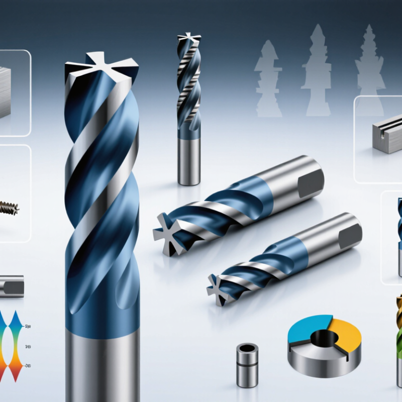
Variable-helix geometry changes how an end mill enters and leaves the workpiece. Helix angles commonly range from 30° to 50°. Unequal pitch spaces the flutes at different angular intervals. For example, a cutter may use 38°, 42°, and 46° flute spacing.
This disrupts synchronized tooth impacts. The result can be lower harmonic vibration, especially in thin walls, deep pockets, and long tool extensions. A 2023 CIRP Journal review linked variable pitch with reduced forced vibration in milling, although results depended on tool rigidity and cutting conditions. Small details matter. A 12 mm cutter with a 45° helix may cut smoothly in aluminum, yet chatter in stainless steel when overhang doubles.
I check radial depth, axial engagement, workholding, and spindle speed before selecting geometry. Unequal pitch cannot repair weak fixturing. That is easy to forget. The U.S. Geological Survey’s Mineral Commodity Summaries 2024 reported about 81,000 metric tons of global tungsten mine production in 2023. This reinforces the value of extending carbide tool life through controlled vibration and stable chip evacuation. However, a higher helix is not automatically better. Angles near 50° improve shearing in some aluminum cuts but may weaken the cutting edge or increase axial pull. For hardened steel, a 30°–35° helix can offer better edge support. Actual trials still matter. Record sound, spindle load, flank wear, and wall finish during the first test cut.
| Selection Dimension | Typical Geometry or Range | Primary Benefit | Suitable Applications | Important Considerations |
|---|---|---|---|---|
| Variable helix angle | Approximately 30°–50° along or between flutes | Spreads tooth-passing energy across different frequencies and helps reduce harmonic chatter | Slotting, profiling, shoulder milling, and adaptive roughing where vibration is a concern | A variable helix does not replace proper workholding, tool runout control, or correct speeds and feeds |
| Unequal pitch | Uneven circumferential spacing between cutting edges | Reduces synchronized tooth impacts and may improve milling stability | Long-reach profiling, thin-wall components, and machines with limited rigidity | The exact pitch pattern is tool-specific; verify the recommended cutting data before production use |
| 30°–35° helix | Low-to-medium helix section within a variable-helix design | Balanced cutting action with comparatively moderate axial force | General-purpose milling of steels, cast irons, and moderately difficult alloys | Often a practical starting point when edge strength and general versatility are priorities |
| 35°–45° helix | Medium helix range commonly used in variable-helix milling tools | Good compromise among chip evacuation, surface finish, and cutting stability | Side milling, contouring, pocketing, and mixed roughing/finishing operations | Confirm flute count and core design because helix angle alone does not determine performance |
| 45°–50° helix | High-helix section within a variable-helix geometry | Improves shearing action and chip lifting, particularly in ductile materials | Aluminum, copper alloys, titanium, stainless steels, and other materials where chip evacuation is important | Higher helix angles can increase axial forces; secure clamping and suitable toolpath strategies are essential |
| Flute count | 2–3 flutes for chip space; 4–6 flutes for productivity and finishing | Controls chip clearance, feed capacity, edge engagement, and surface-finish potential | Choose fewer flutes for deep slotting or high-volume chips; choose more flutes for profiling and finishing | The correct choice depends on material, radial engagement, axial depth, coolant, and machine power |
| Core and web thickness | Standard or reinforced core selected for the tool diameter and cutting load | Improves bending resistance and supports stable heavy cutting | High axial depth, hard materials, interrupted cuts, and extended-reach operations | A stronger core usually reduces flute space, so chip evacuation must be checked |
| Tool diameter and reach | Use the largest practical diameter and the shortest practical overhang | Raises bending stiffness and reduces deflection and vibration | All milling operations, especially deep cavities and thin-wall components | Long-reach tools require conservative engagement, secure holding, and careful runout control |
| Workpiece material | Match helix, flute count, edge preparation, and coating to material behavior | Balances wear resistance, heat management, chip evacuation, and edge security | Aluminum alloys, steels, stainless steels, cast irons, titanium alloys, and nickel-based alloys | Ductile materials typically need stronger chip evacuation; abrasive or hardened materials need wear-resistant edges |
| Cutting engagement | Adjust radial and axial engagement to machine rigidity and tool diameter | Helps control heat, cutting force, deflection, and chip thickness | Adaptive roughing, dynamic milling, conventional pocketing, and finishing | Use manufacturer-recommended starting values; do not transfer data between tools solely because angles are similar |
| Primary decision rule | Select geometry based on material, operation, rigidity, reach, and required finish | Provides a more predictable balance of stability, productivity, tool life, and finish quality | Production milling where chatter reduction and reliable chip control are important | Test the selected tool under representative conditions and monitor sound, load, burrs, finish, and wear |
Note: Helix-angle ranges and unequal-pitch patterns are not universal standards. Actual performance depends on tool diameter, substrate, coating, edge preparation, flute count, runout, machine dynamics, workholding, coolant, and programmed cutting parameters.
It uses changing helix angles, often 30° to 50°, and unequal flute spacing. A cutter might use 38°, 42°, and 46° spacing. This interrupts synchronized tooth impacts and may reduce harmonic vibration.
It can help in thin walls, deep pockets, and long tool extensions. The benefit depends on rigidity, engagement, and workholding. Not a cure-all.
No. A 45° or 50° helix may shear aluminum smoothly. It can also weaken the edge or increase axial pulling force. For hardened steel, 30°–35° may provide stronger edge support. Test the actual cut.
Match hardness and toughness to the workpiece and cutting conditions. Harder carbide resists abrasive wear but may chip during interrupted cuts. Tougher carbide tolerates vibration but can wear sooner. That trade-off is easy to miss.
Check heat limits, oxidation resistance, friction behavior, and thermal-shock resistance. Dry, high-speed cutting needs sustained heat resistance. Coolant-based cutting may demand thermal-shock resistance. Temperature ratings alone can mislead.
Use cutting data as a starting point, not an absolute answer. For a 10 mm cutter at 120 m/min, speed is about 3,820 RPM. With four flutes and 0.05 mm/tooth, feed is about 764 mm/min. Formula: RPM × flutes × chip load. Keep it visible.
Listen for chatter, check spindle load, inspect flank wear, and examine wall finish. Powdery chips may indicate rubbing. Long, blue chips may show excessive heat. Record one change at a time.
No. Weak fixturing, a flexible holder, or excessive projection can still create chatter. A rigid setup helps reveal the tool’s real performance. I once blamed the coating too quickly. The projection was excessive.
Record tool diameter, material, RPM, feed, engagement, coolant, passes, and flank wear. Measure the edge, not only surface finish. Small notes expose patterns. My records are not perfect, but they prevent repeated guesses.
Choosing the right variable-helix end mill begins with understanding its geometry. Helix angles commonly range from 30° to 50°, while unequal flute pitch helps distribute cutting forces and reduce harmonic vibration. To match the tool to chatter risk, consider a pitch variation of approximately 8°–12%, then select carbide grade and coating characteristics according to the workpiece hardness, cutting temperature, and required wear resistance. These factors help determine whether the tool can maintain edge strength and consistent performance during demanding machining.
The question “what is the advantage of variable helix end mills” is answered through improved stability, lower chatter, better surface finish, and potentially longer tool life. However, these benefits depend on correct operating conditions. Set spindle speed, feed rate, and chip load using reliable manufacturer cutting data, then verify results through ISO 8688 tool-life testing. Comparing tool life, machining time, and total cost per part provides a practical basis for confirming whether the selected tool delivers measurable production value.

 Tier Tool