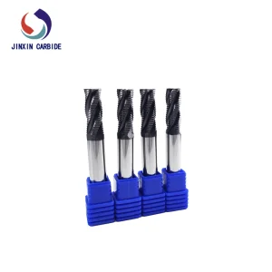
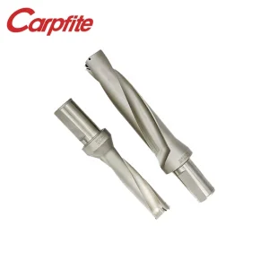
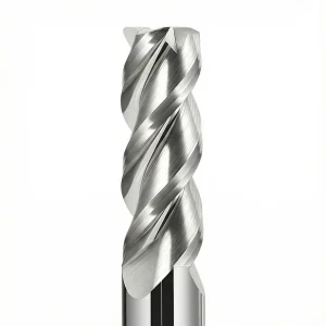
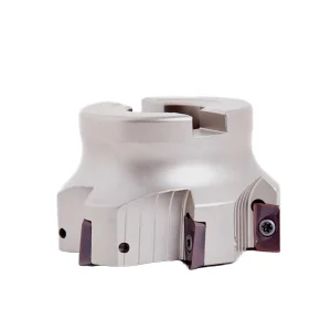
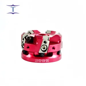
Engineered for ultimate rigidity, optimized geometry, and maximum chip evacuation rates in heavy-metal removal.
The modern metalworking landscape has undergone a tectonic shift, evolving from standardized, low-feed milling setups to complex high-speed machining (HSM) systems. Globally, heavy industries such as aerospace, electric vehicles (EVs), medical technology, and micro-die casting mold production are demanding unprecedented surface finish qualities and tighter geometric tolerances. At the heart of these micro-geometric features are custom angle end mills—often referred to as tapered end mills, chamfering tools, and compound relief cutters.
Historically, standard tools struggle with specialized machining tasks such as drafting mold walls, deep contour beveling, or complex multi-axis profiling. The mechanical stress concentrated on standard square end mills when executing angled passes frequently leads to premature tool deflection, chatter, and dynamic run-out errors. By adopting dedicated, geometrically optimized angle end mills, industrial factories minimize step-marks, improve dimensional control over draft angles, and achieve exceptional E-E-A-T benchmark-grade output.
Furthermore, the optimization of machining parameters depends heavily on tool-substrate harmony. Today’s international supply chain demands that solid carbide tools are manufactured to exact, repeatable geometric patterns, ensuring that automation loops in automated factories run without intervention. In terms of macro-industrial requirements, factories are no longer seeking generic tools; they demand customizable profiles designed specifically for their alloys—whether it is 7075-T6 aluminum, Inconel 718, or pre-hardened mold steel.
The performance of an angle end mill is determined by its micro-geometry. For manufacturers specializing in OEM and ODM custom setups, the design phase must focus on two vital engineering metrics:
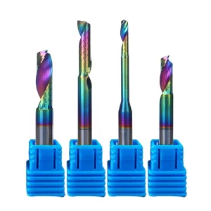
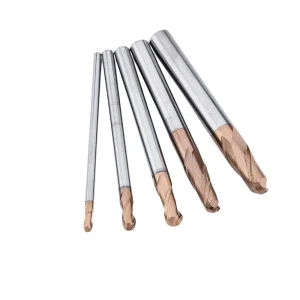
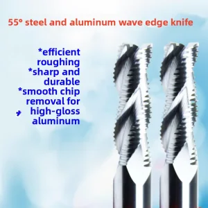
The choice of helix angle (ranging from 30° to 45°, and occasionally variable helix setups) directly affects chip load, heat dissipation, and vibrational harmonics.
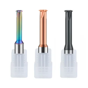
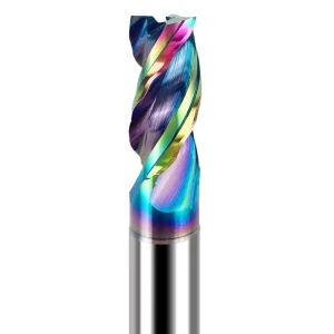
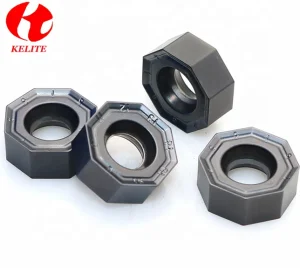
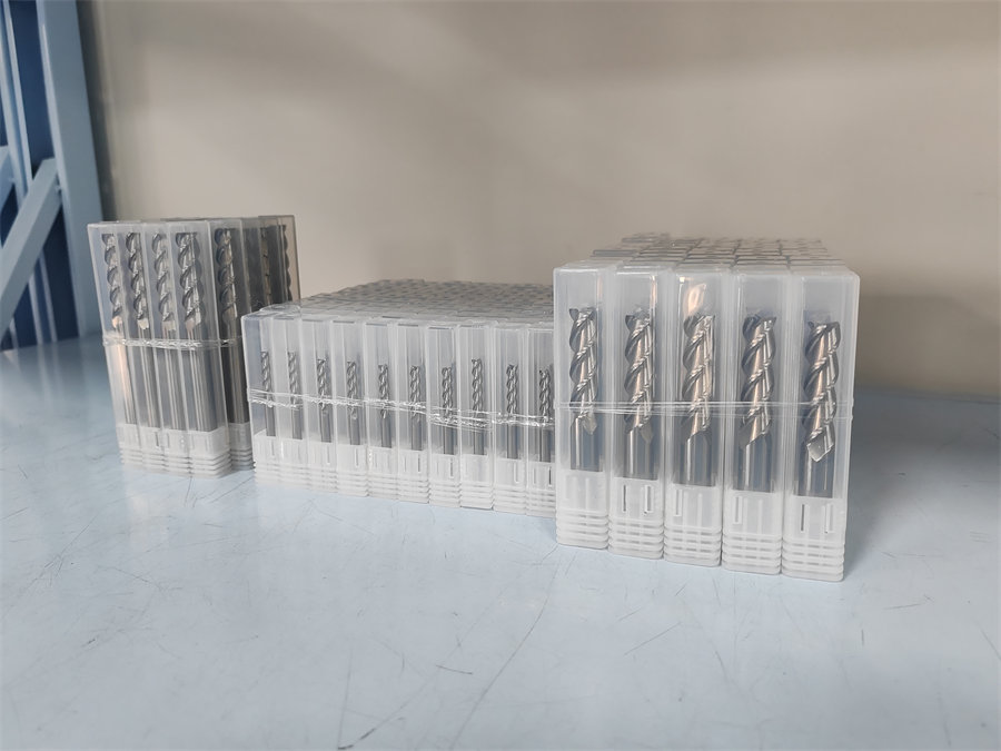
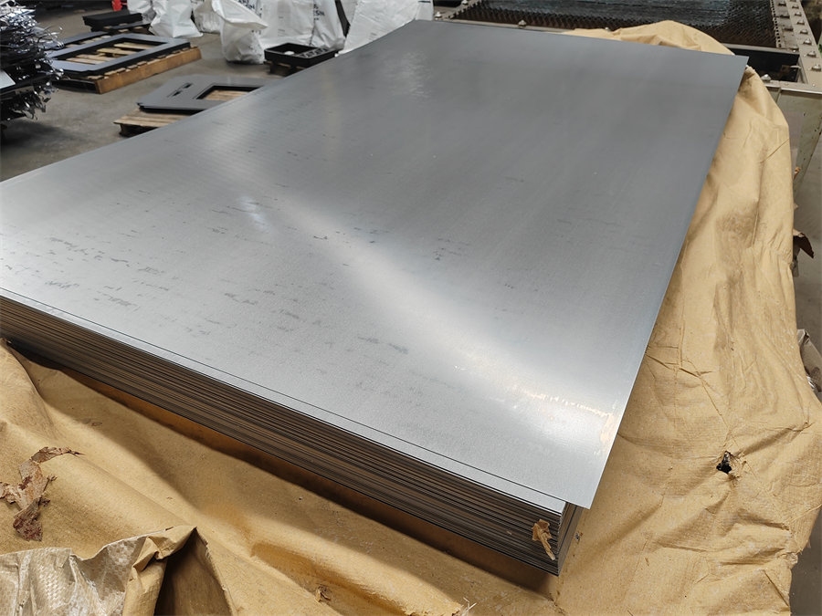
Substrates act as the structural foundation of the tool. Suzhou Tier Tool utilizes ultra-fine grain tungsten carbide (with grain sizes below 0.6 microns) combined with premium cobalt binders to maximize toughness and hardness. However, even the best carbide substrate needs a heat-resistant coating to survive high-speed dry milling environments:
Off-the-shelf catalog tools often fall short when dealing with non-standard mold profiles and proprietary alloy components. This gap makes bespoke OEM/ODM manufacturing partnerships crucial for leading manufacturers.
The customized tooling lifecycle follows a strict technical engineering sequence:
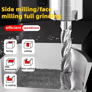
With custom tooling solutions, manufacturers can combine roughing, profiling, and chamfering stages into a single multi-functional tool, reducing cycle times and minimizing tool-change downtime.
Suzhou Tier Tool Co., Ltd. was established in 2008 and is a national high-tech enterprise specializing in the design, manufacturing, and technical support of precision solid carbide cutting tools. Since its foundation, Tier Tool has been deeply committed to the precision machining industry, focusing on delivering high-performance, high-efficiency cutting solutions for hole-making and metalworking applications. Through continuous technological innovation and manufacturing excellence, the company has earned the trust of customers across a wide range of industries worldwide.
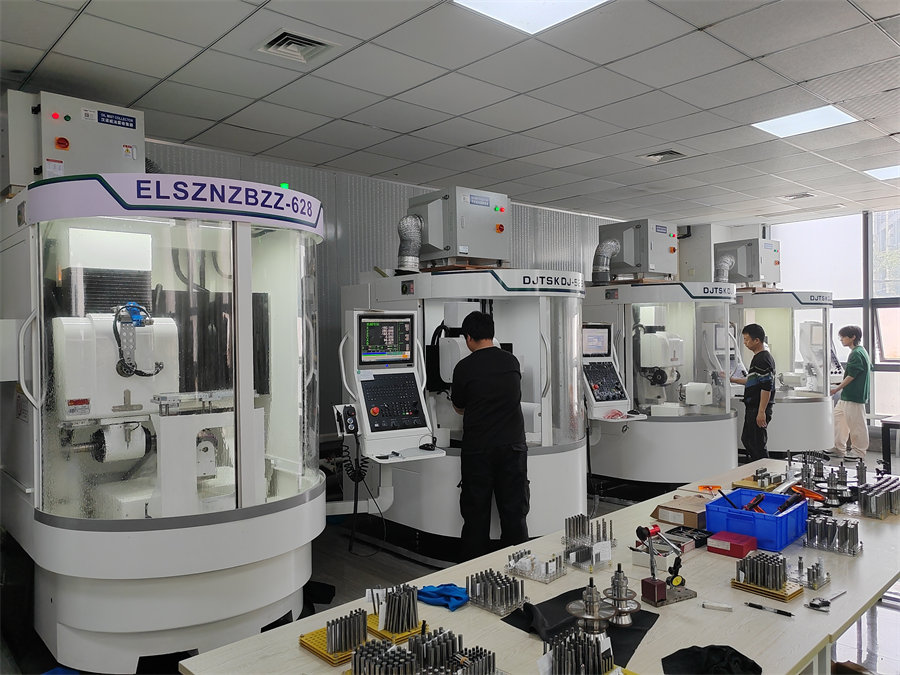
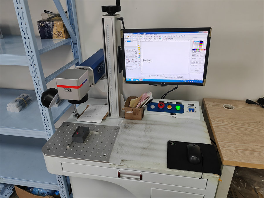
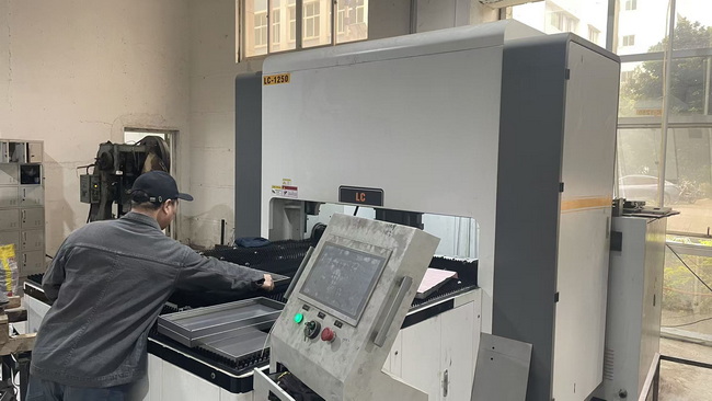
Our manufacturing facility operates multiple imported CNC tool grinding machines and precision inspection systems, enabling complete in-house capabilities from tool design and prototyping to small-batch testing and large-scale production. Every production stage is carefully monitored to ensure repeatability, quality consistency, and reliable delivery performance. Through systematic process management and standardized operating procedures, Tier Tool has established a robust manufacturing system capable of meeting the demanding requirements of modern precision machining.
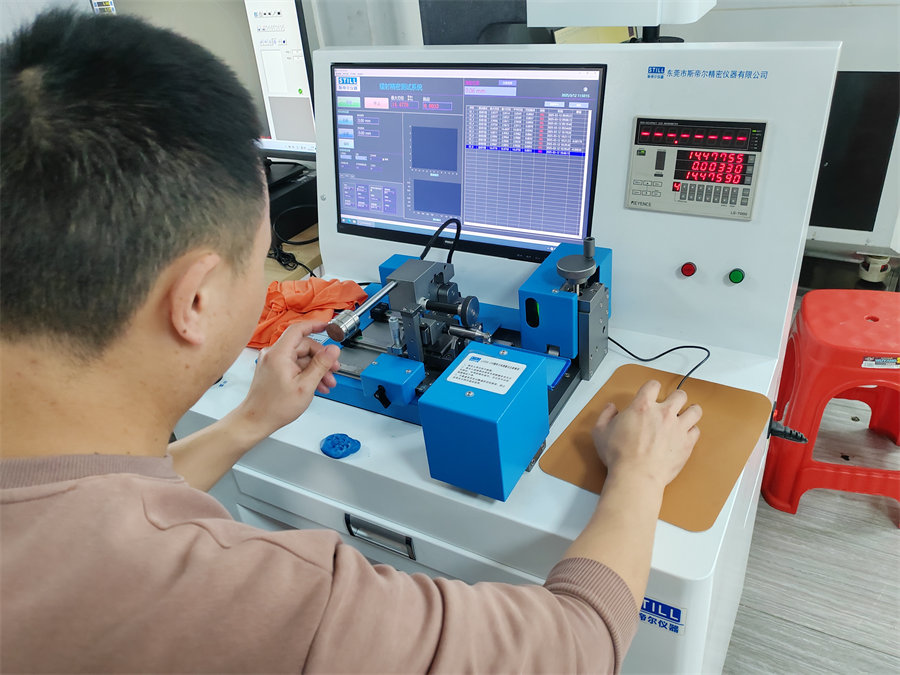

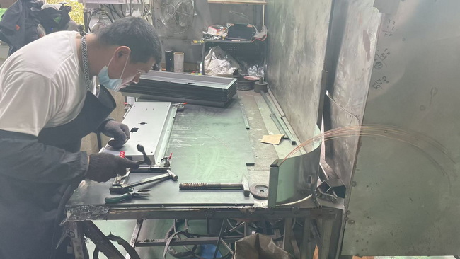


Quality is the foundation of Tier Tool's long-term success. We adhere to the principle of "Quality First, Continuous Improvement", implementing rigorous quality control procedures throughout the entire production cycle. From raw material selection and incoming inspection to final product verification, every tool undergoes comprehensive quality checks to ensure it meets strict dimensional, geometrical, and performance requirements. By continuously optimizing our manufacturing and inspection processes, we deliver products that provide exceptional accuracy, reliability, and consistency in real-world machining applications.
Procuring advanced machinery cutting tools involves navigating complex international trade requirements and strict industry compliance frameworks. For high-precision components used in aerospace and medical implants, tooling suppliers must provide full material traceability and guarantee adherence to environmental regulations like RoHS and REACH, alongside quality management systems like ISO 9001:2015.
Understanding localized application scenarios is equally critical:
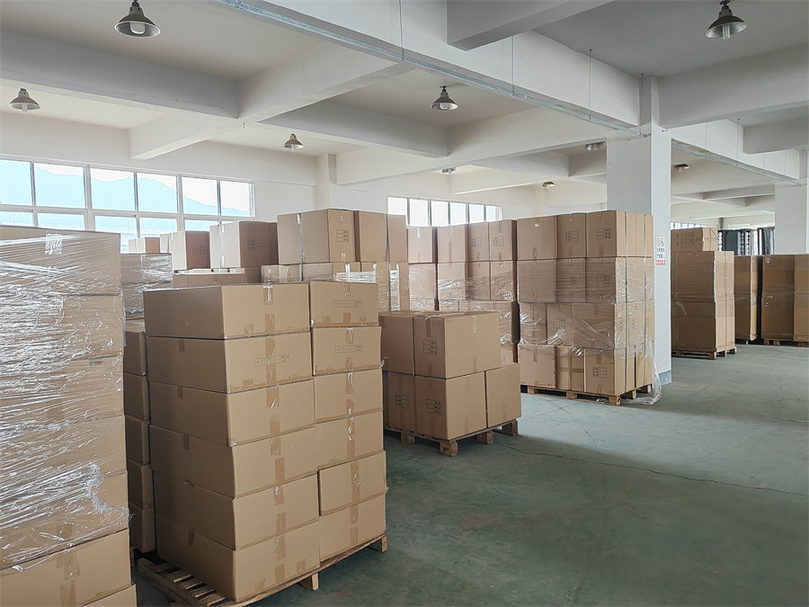
To protect global operations against supply chain interruptions, Suzhou Tier Tool provides flexible safety-stock buffering, dedicated regional distribution support, and reliable logistics channels. This ensures your production lines run continuously, without unexpected downtime.
Professional engineering answers addressing common milling challenges, coating selections, and customization procedures.
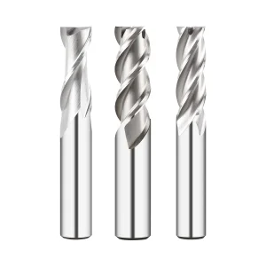
Engineered for heavy stock removal and high-efficiency milling across steel, aluminum, and cast iron alloys.